Fisher Layouts
Headstone Viaduct
IntroductionPhase 1 - Headstone Viaduct
Exhibition Managers Information
Exhibitions Attended/Invited
Introduction
I have always enjoyed railways through hills, and spent many holidays around the Settle and Carlisle. I wanted to model such a scene, but S & C layouts were commonplace at the time. The answer was to look to my home county and model the Peak Mainline. Various scheme have been toyed with and rejected. Ambergate was my first thought, but thats now been done. Stan Roberts has built Bakewell, and I know someone is working on Millers Dale.Doesn't leave a lot.
I had often thought of Monsal Dale, but the station didn't have enough to interest me. Then I read an article, on RMWeb I believe, about the building of the viaduct on Black Country Blues, and my attention switched to Monsal Dale Viaduct.
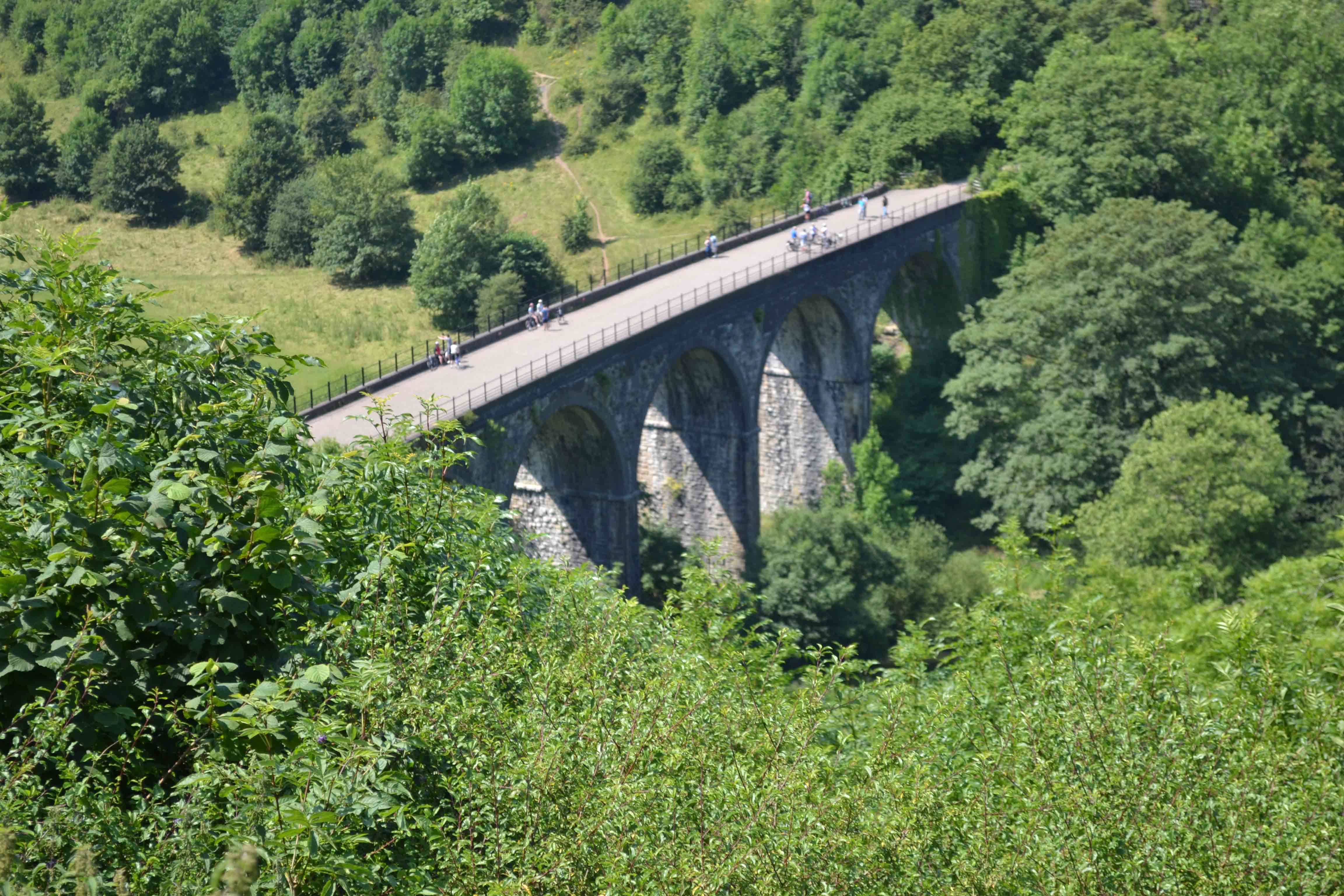
Anyone who knows Monsal Dale will know that the railway comes out of Headstone Tunnel onto a short embankment, across the viaduct and then into a cutting just before Monsal Dale Station. When they built the line the Midland Railway obligingly put a bridge over the line just before the end of the cutting. So there is the layout defined tunnel mouth to overbridge.
Another layout could be built from the overbridge to Cressbrook Tunnel, incorporating Monsal Dale Station. The whole distance from Headstone Tunnel to Cressbrook Tunnel is about 1 mile or 72 feet in 4mm. So when the layout is complete, it can be shown as Headstone Viaduct or Monsal Dale Station or Monsal Dale including Headstone Viaduct.
Phase 1 - Headstone Viaduct
The scenic section for phase 1 will be about 20 feet long and will stretch from Headstone Tunnel to the overbridge. It will incorporate Headstone Viaduct and the point where the valley and river turn sharp right.
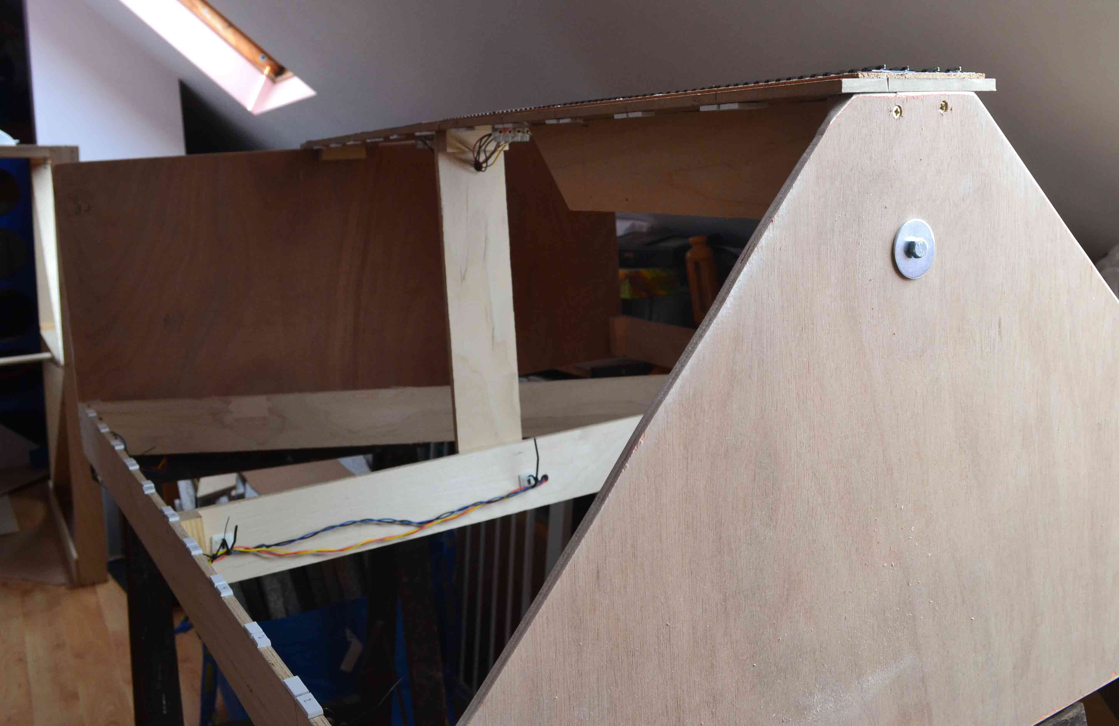
The boards are made from 9mm ply side rails 75mm thick and end boards cut to suit the site. Diagonal bracing has been installed where required. The trackbed is from old unused laminate flooring panels cut to follow the track line. 9mm x 75mm risers support the trackbed in the middle of the boards.
The layout is controlled via DCC, with the up and down lines wired as two separate systems, so that we can keep something running if we experience a problem. The cables are kept to the inside of the layout, so that they are kept clear of the joining bolts. Breakout from the bus takes place at the bottom of a riser and goes to a screw down connector by the dropper from the track above.
.
Droppers are soldered to the underneath of the rail before the track is laid, and is arranged so that the wire disappears through the base of the nearest chair. This makes the wiring virtually invisible. Each panel of track has its own independant feed so we have no need of functional fishplates.
Exhibition Managers Information
At present the layout is still under construction, but will be:-
- To 4mm scale EM gauge.
- Size is not finalised but will be in the order of 30ft long by 11ft wide.
- The layout will be primarily operated from the middle and behind so requires (ideally) 30ft by 12ft.
- Lightweight, constructed from Plywood and foamboard, quick and simple to erect and knockdown.
- Single power supply required.
- It can be operated by 4 but ideally 6 operators.
- Attendance for expenses only, (transported in a small van from South Essex).
- It is equipped for full DCC operation.
- Operational period will be August 1938.
Exhibitions Attended/Invited
None, yet..!